
Variable DC Power Supply with 2N3055

This is variable power supply for multi purpose usage and very useful to supply your electronic tools or your projects. Voltage range will be 0.7 - 24V and the urrent limiting range is 50mA - 2A.
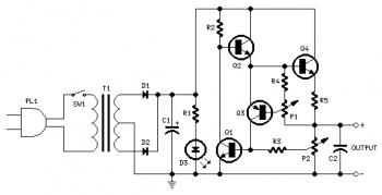
Variable DC Power Supply with 2N3055 circuit diagram

Components:

P1____________500R   Linear Potentiometer
P2_____________10K Log. Potentiometer

R1,R2__________2K2 1/2W Resistors
R3____________330R 1/4W Resistor
R4____________150R 1/4W Resistor
R5______________1R 5W Resistor

C1__________3300µF 35V Electrolytic Capacitor (see Notes)
C2_____________1µF 63V Polyester Capacitor

D1,D2_______1N5402 200V 3A Diodes
D3____________5mm. Red LED

Q1___________BC182 50V 100mA NPN Transistor
Q2___________BD139 80V 1.5A NPN Transistor
Q3___________BC212 50V 100mA PNP Transistor
Q4 _________2N3055 60V 15A NPN Transistor

T1____________220V Primary, 36V Center-tapped Secondary
50VA Mains transformer (see Notes)
PL1___________Male Mains plug
SW1___________SPST Mains switch

Notes:

  • P1 sets the maximum output current you want to be delivered by the power supply at a given output voltage.
  • P2 sets the output voltage and must be a logarithmic taper type, in order to obtain a more linear scale voltage indication.
  • You can choose the Transformer on the grounds of maximum voltage and current output needed. Best choices are: 36, 40 or 48V center-tapped and 50, 75, 80 or 100VA.
  • Capacitor C1 can be 2200 to 6800µF, 35 to 50V.
  • Q4 must be mounted on a good heatsink in order to withstand sustained output short-circuit. In some cases the rear panel of the metal box in which you will enclose the circuit can do the job.
  • The 2N3055 transistor (Q4) can be replaced with the slightly less powerful TIP3055 type.

Comments

Popular posts from this blog

LM317T Voltage Regulator Circuit with Pass Transistor

This is the schematic diagram of voltage regulator circuit with pass transostor. The regulator is based regulator IC of LM317T. The LM317T output current can be raised by utilizing an additional power transistor (on circuit, it is 2N2955) to share a portion of the total current. The amount of current sharing is established with a resistor placed in series with the LM317 input and a resistor placed in series with the emitter of the pass transistor. In the above scheme design , the pass transistor will start conducting when the LM317 current reaches about 1 ampere, due to the voltage drop across the 0.7 ohm resistor. Current limiting happens at about 2 amperes for the LM317 which will drop about 1.4 volts across the 0.7 ohm resistor and make a 700 millivolt drop across the 0.3 ohm emitter resistor. Thus the total current is limited to about 2+ (.7/.3) = 4.3 amperes.

Sealed Lead Acid (SLA) 12V Battery Charger with Current Limiting

This is the circuit design of Smart Sealed Lead Acid (SLA) 12V Battery Charger featuretwith Current Limiting. The charger uses a two step process for charging SLA batteries – a current limited ‘fast’ mode followed by a constant voltage ‘float’ mode. Maximum charging current is 1A. An onboard LED indicates when the charger is in ‘fast’ mode. When the LED goes out the battery is charged and the charger has switched to ‘float’ mode.

Unregulated Dual Polarity Power Supply

This is the schematic diagram of Unregulated Dual Polarity power supply . Unlike 78xx and 79xx dual polarity regulated power sypply and LM317/LM337 dual polarity regulated power supply which have limited current output and voltage (have limited supply power), this unregulated power supply will give you more power. This kind of circuit usually used for power amplifier which need high supply power, or as high current lead acid battery charger (single polarity only). The component value is flexible refer to your needs. For example: if you need power supply for 100W amplifier, then the component value are: Transformer: 3A minimum (center tap) Diodes: 3A diode (1N5401, 1N5402, 1N5403 etc) Electrolytic capacitor: 4x minimum of 4700uF/50V (the higher is better - check the capacitor voltage, change it for higher voltage. example: use 63V capacitors for 45V power supply output.)