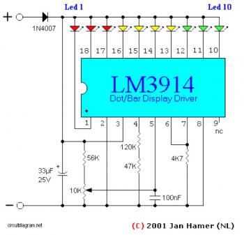
This simple circuit makes it posible to monitor the charging process to a higher level. If you need more information then check out the LM3914 Datasheet.
Final adjustsments are simple and the only thing needed is a digital voltmeter for the necessary accuracy.
Connect an input voltage of 12.65 volt between the positive and negative poles and adjust the 10K trimmer potentiometer until Led 10 lights up. Lower the voltage and in sequence all other Led's will light up. Check that Led 1 lights up at approximately 11.89 volts. At 12.65 volt and higher the battery is fully charged, and at 11.89 is considered 'empty'.
The green Led's indicate that the battery capacity is more than 50%, the yellow Led's indicate a capacity of 30% - 50% and the red Led's less that 30%. This circuit, with the components shown, uses less than 10mA. Of course you can adapt this circuit to your own needs by making small modifications. The circuits above is set for 'DOT' mode, meaning only one Led at a time will be lit.
If you wish to use the 'BAR' mode, then connect pin 9 to the positive supply rail, but obviously with increased current consumption.
The LED brightness can be adjusted up- or down by choosing a different value for the 4K7 resistor connected at pin 6/7.
You can also change the to monitoring voltage level. For example, let's say you wanted to change to 10 - 13 volt, you connect 13volt to the input (+ and -) and adjust the 10K potentiometer until Led 10 lights up. Change temporarily the resistors at pin 4 with a 200 Kilo-ohm potentiometer and reconnect a voltage from 10 Volt to the input. Now, re-adjust the 200K potentiometer until Led 1 lights up. When you are satisfied with the adjustment, feel free to exchange the 200K potentiometer with resistors again.(after measuring the resistance from the pot, obviously).
The diode 1N4007 was included to protect the circuit from a wrong polarity connection. It is however strongly recommended to connect the monitor directly to the battery, in principle a connection to the cigarrette lighter would suffice but for reasons unknown at this time the voltage at that point is 0.2 volt lower than the voltage measured directly on the battery.

Comments