
1.5V-25V DC Variable Power Supply

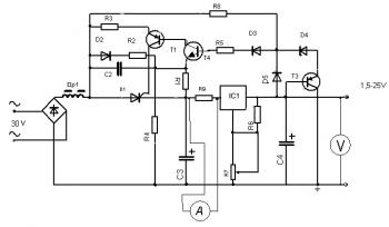
This is 1.5V-25V DC Variable Power Supply. The power supply use KR142EN14 or LM317 as regulator component. KR142EN14 or LM317 is capable to handle electric current up to 2A. You may use LT1083/84/85 to handle electric current of 7A/5A/3A. Resistor R9 is used as a current sensor to an ammeter.

electronic circuit diagram

Components list:
R1 : 4K3
R2 : 18K
R3 : 100
R4,R8 : 100K
R5 : 1K
R6 : 240
R7 : 4K7 ( Variable resistor )
R9 : 0.33 E
C2 : 0.1uF
C3 : 10000uF/40V
C4 : 100uF/25V
D1 : KY202
D2 : KD521
D3 : D311
D4 : KC147
T1 : KT814B
T3 : KT209
T4 : KT3102
IC1 : KR142EN14 (LM317)


Circuit source: 1.5V-25V power supply with preregulator

Comments

Popular posts from this blog

LM317T Voltage Regulator Circuit with Pass Transistor

This is the schematic diagram of voltage regulator circuit with pass transostor. The regulator is based regulator IC of LM317T. The LM317T output current can be raised by utilizing an additional power transistor (on circuit, it is 2N2955) to share a portion of the total current. The amount of current sharing is established with a resistor placed in series with the LM317 input and a resistor placed in series with the emitter of the pass transistor. In the above scheme design , the pass transistor will start conducting when the LM317 current reaches about 1 ampere, due to the voltage drop across the 0.7 ohm resistor. Current limiting happens at about 2 amperes for the LM317 which will drop about 1.4 volts across the 0.7 ohm resistor and make a 700 millivolt drop across the 0.3 ohm emitter resistor. Thus the total current is limited to about 2+ (.7/.3) = 4.3 amperes.

Sealed Lead Acid (SLA) 12V Battery Charger with Current Limiting

This is the circuit design of Smart Sealed Lead Acid (SLA) 12V Battery Charger featuretwith Current Limiting. The charger uses a two step process for charging SLA batteries – a current limited ‘fast’ mode followed by a constant voltage ‘float’ mode. Maximum charging current is 1A. An onboard LED indicates when the charger is in ‘fast’ mode. When the LED goes out the battery is charged and the charger has switched to ‘float’ mode.

Unregulated Dual Polarity Power Supply

This is the schematic diagram of Unregulated Dual Polarity power supply . Unlike 78xx and 79xx dual polarity regulated power sypply and LM317/LM337 dual polarity regulated power supply which have limited current output and voltage (have limited supply power), this unregulated power supply will give you more power. This kind of circuit usually used for power amplifier which need high supply power, or as high current lead acid battery charger (single polarity only). The component value is flexible refer to your needs. For example: if you need power supply for 100W amplifier, then the component value are: Transformer: 3A minimum (center tap) Diodes: 3A diode (1N5401, 1N5402, 1N5403 etc) Electrolytic capacitor: 4x minimum of 4700uF/50V (the higher is better - check the capacitor voltage, change it for higher voltage. example: use 63V capacitors for 45V power supply output.)