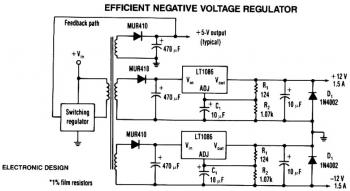
This is the efficient negative voltage regulator circuit built based IC LT1086.
One way to provide good negative-voltage regulation is with a low-dropout positive-voltage regulator operating from a well-isolated secondary winding of switch-mode circuit transformer. The technique works with any positive-voltage regulator, although highest efficiency occurs with low-dropout types.
Under all loading conditions, the minimum voltage difference between the regulator VIN and V0UT pins must be at least 1.5V, the LT1086's low-dropout voltage. If this requirement isn't met, the output falls out of regulation. Two programming resistors, R1 and R2, set the output voltage to 12 V, and the LT1086's servo the voltage between the output and its adjusting (ADJ) terminals to 1.25 V. Capacitor C1 improves ripple rejection, and protection diode D1 eliminates common-load problems.
Since a secondary winding is galvanically isolated, a regulator's 12 V output can be referenced to ground. Therefore, in the case of a negative-voltage output, the positive-voltage terminal of the regulator connects to ground, and the -12 V output comes off the anode of D1. The VIN terminal floats at 1.5 V or more above ground.
LT1086 Negative voltage regulator circuit diagram.

Comments