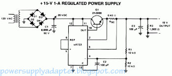
This is the design diagram of +15V / 1A regulated power supply using uA723.
Circuit operation: The supply receives +20VDC from the rectifier / filter section (diode bridge). This is applied to pins 11 and 12 of the IC uA723, as well as to the collector of the 2N3055 series-pass transistor. The output voltage is simpled through R1 and R1, providing about 7V with respect to ground at pin 4. The reference terminal at pin 6 is tied directly to pin 5, the noninverting input of the error amplifier. For fine tuning output voltage, a potensiometer can be installed between R1 and R2. A 100 pF capacitor to pin 4 furnishes gain compesation for the amplifier.
Base drive to the 2N3055 pass transistor is furnished by pin 10 of the uA723. Since the desired output of the power supply is 1A, the maximal current limit is set to 1.5A by the resistor Rsc whose value is 0.433 Ohm.
A 100uF electrolytic condensator is used for ripple voltage reduction at the output. A 1K Ohm output resistor give stability for the power supply while in "no load" condition. The 2N3055 pass transistor have to be mounted on an adequate headsink for it stability and prevent overheating.

Comments