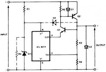
Here the schematic diagram of positive regulator with PNP and NPN transistor boost. Inside the circuit, Q1 and Q2 are wired in the classic SCR or thyristor configuration. In which higher input voltages or minimum element count are needed, the circuit for thyristor boost could be applied. The thyristor is working in a linear mode with its cathode as the control terminal and its gate to be the output terminal. This is known to be the remote base configuration.
Here the schematic diagram of positive regulator with PNP and NPN transistor boost. Inside the circuit, Q1 and Q2 are wired in the classic SCR or thyristor configuration. In which higher input voltages or minimum element count are needed, the circuit for thyristor boost could be applied. The thyristor is working in a linear mode with its cathode as the control terminal and its gate to be the output terminal. This is known to be the remote base configuration.

Comments