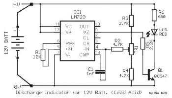
Here the discharge indicator circuit for Lead Acid battery 12V. This circuit is used to prevent the batteries from damage. When discharging the battery voltage pin 12V Lead may not be reduced below 10.8V, so we notice the lighting of Led, when the voltage falls below this value. To achieve control we need a constant voltage and a circuit that can compare this with the controlled voltage. And these two conditions to ensure the IC1-LM 723.
The input terminals of the circuit connected to the battery terminals. In IC1/6 shows a steady trend of +7.15 V, when the input voltage is greater than + 9.5V. The constant voltage is applied to IC1/5. In IC1/4 applies a voltage of the input, controlled by the trimmer TR1. The IC1 is act as voltage comparator . So when the voltage at IC1/4 is greater than the voltage at IC1/5, then the output of IC1/9, is low [L], the Q1 is off and the LED is off. To turn the LED should the voltage at IC1/4 be less than the reference voltage at IC1/6, where the output of IC1/9 will be high [H], the Q1 conducts and LED lights.
To configure the circuit will need an external power supply, which will be configured to output a +10.8 V, we apply the input circuit. Adjust the trimmer TR1, so that lights the LED, with no decrease in the voltage of power supply. The input terminals of the circuit should be connected directly to the battery terminals and may be used when using batteries 12V (Lead Acid).

Comments