Here the schematic design diagram of 600V power supply for QRO HF amplifiers. Amateur Radio Transmitters working with valves such as 807 or1625 operates properly using a plate voltage in between 600V to 700 Volts. The circuit described below is actually a full wave voltage doubler. The output voltage is twice the input voltage. For 230V AC input the output is going to be close to 600 Volts.
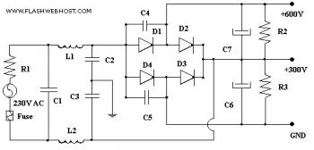
Resister R1 is applied to minimize the initial high voltage and high currents. Capacitor C1, C2, C3 along with coils L1 and L2 form input line filter. The capacitors C4 and C5 protects diodes from high voltage transients on the AC line as well as minimizes inter carrier hum modulation of the R.F picked up by the mains. Capacitors C6 and C7 gives sufficient filtering for the output DC Voltage.
Parts List:
C1, C2, C3 = 0.1 mf 630V
C4, C5 = 0.01 mf 630V
C6, C7 = 100 mf 450V
R1 = 10E 5W Wire Wound
R2, R3 = 220KE 2Watts
D1, D2 = BY127
D3, D4 = BY127
L1, L2 = 12 Turns 18 SWG, Wound over 4 Cm, long Ferrite Rode.
600V power supply for QRO HF amplifiers, circuit source:
http://www.flashwebhost.com/circuit/600_volt_power_supply.php
Comments