Lithium-ion (Li-ion) Battery Charger with MAX1879

Lithium-ion (Li-ion) Battery Charger with MAX1879

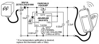
Above diagram is the circuit of Lithium-ion (Li-ion) battery charger which built based single chip MAX1879. This is the simple and low cost battery charger for single-cell Li+ battery that does not dissipate power (no heat.

The MAX1879, in conjunction with the AC linear transformer adapter and a PMOS FET, allows safe and fast charging of a single Li+ cell. The MAX1879 is not only an inductorless required solution, but also the lowest power dissipated solution among single-cell Li+ battery chargers.

The MAX1879 with a current limited linear wall adapter can produce the most economic and efficient solution for the single-cell Li+ off-line cradle charger, with virtually no power loss on the PMOS FET. It can be easily designed for handheld devices or battery packs without excessive power dissipation and heat problems.

Read detailed explanation about this Lithium-ion (Li-ion) battery charger circuit at maxim-ic.com

About MAX1879:
The MAX1879 single-cell lithium-ion (Li+) battery charger utilizes an efficient pulse-charging architecture to minimize power dissipation in portable devices. This architecture combines the efficiency of switch-mode chargers with the low cost and simplicity of linear chargers. This simple device, in conjunction with a current-limited wall cube and a PMOS transistor, allows safe and fast charging of a single Li+ cell.

MAX1879 Features:
  • Low Electronic Component Count, No Inductor
  • Simple Design Minimizes Heat
  • 0.75% Accurate Battery Regulation
  • 1.5µA (max) Battery Current Drain with Wall Cube Removed
  • Restart Charging at 4.0V
  • Battery-Full Indicator
  • Safely Precharges Near-Dead Cells
  • Automatic Power-Down when Power Source is Removed
  • Continuous Overvoltage and Overtemperature Protection
  • Charges 1 Cell from as Low as 4.5V
  • Pin-Compatible Upgrade to MAX1679
Download MAX1879 datasheet

Comments

Popular posts from this blog

LM317T Voltage Regulator Circuit with Pass Transistor

This is the schematic diagram of voltage regulator circuit with pass transostor. The regulator is based regulator IC of LM317T. The LM317T output current can be raised by utilizing an additional power transistor (on circuit, it is 2N2955) to share a portion of the total current. The amount of current sharing is established with a resistor placed in series with the LM317 input and a resistor placed in series with the emitter of the pass transistor. In the above scheme design , the pass transistor will start conducting when the LM317 current reaches about 1 ampere, due to the voltage drop across the 0.7 ohm resistor. Current limiting happens at about 2 amperes for the LM317 which will drop about 1.4 volts across the 0.7 ohm resistor and make a 700 millivolt drop across the 0.3 ohm emitter resistor. Thus the total current is limited to about 2+ (.7/.3) = 4.3 amperes.

Sealed Lead Acid (SLA) 12V Battery Charger with Current Limiting

This is the circuit design of Smart Sealed Lead Acid (SLA) 12V Battery Charger featuretwith Current Limiting. The charger uses a two step process for charging SLA batteries – a current limited ‘fast’ mode followed by a constant voltage ‘float’ mode. Maximum charging current is 1A. An onboard LED indicates when the charger is in ‘fast’ mode. When the LED goes out the battery is charged and the charger has switched to ‘float’ mode.

Unregulated Dual Polarity Power Supply

This is the schematic diagram of Unregulated Dual Polarity power supply . Unlike 78xx and 79xx dual polarity regulated power sypply and LM317/LM337 dual polarity regulated power supply which have limited current output and voltage (have limited supply power), this unregulated power supply will give you more power. This kind of circuit usually used for power amplifier which need high supply power, or as high current lead acid battery charger (single polarity only). The component value is flexible refer to your needs. For example: if you need power supply for 100W amplifier, then the component value are: Transformer: 3A minimum (center tap) Diodes: 3A diode (1N5401, 1N5402, 1N5403 etc) Electrolytic capacitor: 4x minimum of 4700uF/50V (the higher is better - check the capacitor voltage, change it for higher voltage. example: use 63V capacitors for 45V power supply output.)