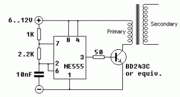
Here the circuit diagram of solid state tesla coil with 555 timer.
Single transistor flyback driver induced a lot of complications on account of it really is operating principle. I received e-mails from those who had been unable to obtain it functional even after they are positive that their flyback and transistor is Okay. Moreover, because it is resonance frequency is determined by each individual a part of the method, any time you seek to draw an arc in the transformer, it alterations substantially in a lot of the circumstances. Simply because the operating frequency is vital for your security criteria, (each for mine and electrical power transistor's), I determined to generate it run on a continuous frequency and developed up yet another easy circuit, attempting to keep within the specified limits in the 555 timer.
Setting the operating frequency with an integrated timer is simple and practical. This schematic is absolutely nothing over the normal astable mode circuit layout having a traditional 555. It calls for only two resistors as well as a capacitor to set frequency (with duty cycle certainly) and a further resistor to ascertain electrical power transistor's base current, which it is possible to uncover it is optimal worth experimentally. I employed 1K for R1, two.2K for R2, and 10nF for C which produced circuit to run practically at 27 kHz theoretically, at %60 higher to %40 minimal duty cycle. You may easily calculate operating parameters in the resistance and capacitor values which has a tiny system that I've written.
Values offered for R1, R2 and C within this circuit diagram would be the ones employed on my prototype. You could possibly transform R1 and use a trimmer as a substitute for R2 to discover an optimum frequency / duty cycle blend to your flyback. By shifting C, you may possess the capacity to use increased or reduced resistor values, but tend not to desire as well minimal resistances (primarily for R1) for to not overload 555.
Energy transistor just isn't significant and any other could be applied so long as it really is qualities are equivalent or greater. Listed below are the technical datas for BD243C for comparison:
Bipolar NPN transistor : BD243C
Casing : TO220
Max. collector current : 6 Amperes
Max. complete energy : 65 Watts, even though situation is at 25 degrees Celsius
Transition frequency : 3 MHz
hFE (current obtain) : 30 at 300mA (minimal value)
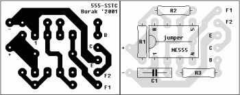
PCB layout:
Detailed explanation about this circuit, visit this page: Solid State Tesla Coil with 555 Timer


Comments