This is about how to increase the current output limit after voltage regulating process using regulator 78xx series. As we know, current output after 78xx regulator is about 1 - 1.5A. With this circuit, you will be able to get higher current output from regulated power supply.
Components List:
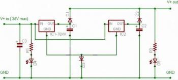
R1, R2 = 4.7 K
C1, C2 = 4700 uF / 16V
C3 = 47,000 uF / 35V
D1,D2, D3 = 1N5401 ( 3 Amp Diodes )
D4 & D5 – Light Emitting Diodes (LED)**
IC1, IC2 – 78xx series regulator IC ( 7805 for 5V, 7812 for 12V etc.)
Visit this page for detailed instruction and explanation how to doubling the current output after regulate the voltage with IC regulator 78xx series.

Components List:
R1, R2 = 4.7 K
C1, C2 = 4700 uF / 16V
C3 = 47,000 uF / 35V
D1,D2, D3 = 1N5401 ( 3 Amp Diodes )
D4 & D5 – Light Emitting Diodes (LED)**
IC1, IC2 – 78xx series regulator IC ( 7805 for 5V, 7812 for 12V etc.)
Visit this page for detailed instruction and explanation how to doubling the current output after regulate the voltage with IC regulator 78xx series.
Comments