
Dual Polarity Power Supply +33V, 0 , -33V

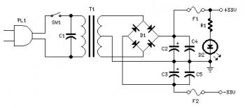
The following diagram is the example of dual polarity power supply circuit which will give you (+33V) ; (0) and (-33V) DC voltage. This circuit is usually used for power amplifier circuit which require dual polarity power supply to work.

Dual Polarity Power Supply +33V, 0 , -33V  circuit diagram


Components List:
R1 = 3K3 1/2W
C1 = 10nF/1000V
C2,C3 = 4700µF/50V
C4,C5 = 100nF/63V
D1 = 200V 8A Diode bridge
D2 = 5mm. Red LED
F1,F2 = 3.15A Fuses with sockets
T1 = 220V Primary, 25 + 25V Secondary, 2A minimum
PL1 = Male Mains plug
SW1 = SPST Mains switch

source: redcircuits.com

Comments

Popular posts from this blog

LM317T Voltage Regulator Circuit with Pass Transistor

This is the schematic diagram of voltage regulator circuit with pass transostor. The regulator is based regulator IC of LM317T. The LM317T output current can be raised by utilizing an additional power transistor (on circuit, it is 2N2955) to share a portion of the total current. The amount of current sharing is established with a resistor placed in series with the LM317 input and a resistor placed in series with the emitter of the pass transistor. In the above scheme design , the pass transistor will start conducting when the LM317 current reaches about 1 ampere, due to the voltage drop across the 0.7 ohm resistor. Current limiting happens at about 2 amperes for the LM317 which will drop about 1.4 volts across the 0.7 ohm resistor and make a 700 millivolt drop across the 0.3 ohm emitter resistor. Thus the total current is limited to about 2+ (.7/.3) = 4.3 amperes.

Sealed Lead Acid (SLA) 12V Battery Charger with Current Limiting

This is the circuit design of Smart Sealed Lead Acid (SLA) 12V Battery Charger featuretwith Current Limiting. The charger uses a two step process for charging SLA batteries – a current limited ‘fast’ mode followed by a constant voltage ‘float’ mode. Maximum charging current is 1A. An onboard LED indicates when the charger is in ‘fast’ mode. When the LED goes out the battery is charged and the charger has switched to ‘float’ mode.

5V to Isolated 5V Converter Circuit

This is the circuit diagram of 5V to Isolated 5V Converter, rated at 20mA electric current. In this converter circuit, a negative output voltage dc to dc converter generates a -5V output at pin A. In order to generate -5V at point A. the primary of the transformer must fly back to a diode drop more negative than -5V. If the transformer has a tightly coupled I : 1 turns ratio. there will be a 5 V plus a diode drop across the secondary. The IN5817 rectifies this secondary voltage to generate an isolated 5V output. The isolated output is not fully regulated since only the -5V at point A is sensed by the MAX635.