This is the schematic diagram of Unregulated Dual Polarity power supply.
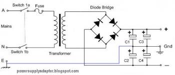
Unlike 78xx and 79xx dual polarity regulated power sypply and LM317/LM337 dual polarity regulated power supply which have limited current output and voltage (have limited supply power), this unregulated power supply will give you more power.
This kind of circuit usually used for power amplifier which need high supply power, or as high current lead acid battery charger (single polarity only).
The component value is flexible refer to your needs. For example: if you need power supply for 100W amplifier, then the component value are:
- Transformer: 3A minimum (center tap)
- Diodes: 3A diode (1N5401, 1N5402, 1N5403 etc)
- Electrolytic capacitor: 4x minimum of 4700uF/50V (the higher is better - check the capacitor voltage, change it for higher voltage. example: use 63V capacitors for 45V power supply output.)
Comments