This is the schematic diagram of UPS CIrcuit for Cordless Telephone:
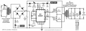
When the AC mains is present, the very same is converted into DC and fed to the inverter. A component of the mains rectified output is being used to charge the battery. When the mains power fails, the DC supply to the inverter is from the battery and from this is obtained AC at the inverter output.
The circuit wired around IC CD4047 is an astable multivibrator operating at a frequency of 50 Hz. The Q and Q outputs of this multivibrator directly drive power MOSFETS IRF540. The configuration applied is push-pull type. The inverter output is filtered as well as the spikes are reduced working with MOV (metal oxide varistor). The inverter transformer chosen is an ordinary 9V-0-9V, 1.5A mains transformer readily offered inside the market. Two LEDS (D6 and D7) indicate the presence of mains/battery.
The mains supply (when present) is stepped down, rectified and filtered working with diodes D1 via D4 and capacitor C1. A component of this supply is also employed to charge the battery. In place of a single 12V, 4Ah battery, one may use two 6V, 4Ah batteries.
The circuit may be easily assembled on a general-purpose PCB and placed inside a metal box. The two transformers may be mounted on the chassis of the box. The identical circuit can deliver up to 100W, provided the inverter transformer and charging transformer are replaced with higher present rating transformers, so that the system may be used for some other applications too.
Download UPS CIrcuit for Cordless Telephone detailed explanation in pdf document here
Comments